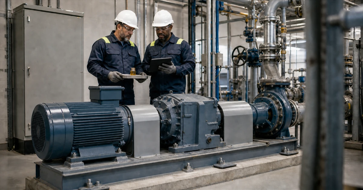

The operating problem
Five reports can agree and still leave the work order wrong.
The vibration analyst flags an input-bearing pattern. Ultrasound is higher at the same housing. Thermography finds a warmer region. The oil report shows more iron. Motor current shifted after a process change. Around the review table, five reports appear to point in one direction, except they were collected at different loads, locations and times. The team has more evidence and still does not have one defensible work scope.
Integrated condition monitoring slows that moment down. It keeps each observation tied to its location, acquisition setup, operating state, time and physical scope. A drive train is coupled, but it can host more than one mechanism at once. The review must test whether one common cause, multiple independent causes or insufficient evidence best fits, then choose an action that can separate those possibilities.
Five trends on one screen are like five maps on one table. Until their location, scale and time agree, the apparent overlap can mislead. The maps do not prove a cause. They show why alignment comes before synthesis.
The real constraint
The hard part is matching evidence to a comparable machine state.
In many connected plants, permanent sensors, handheld routes, oil-laboratory reports, thermal surveys, historian tags, motor-control data and maintenance records already exist. A practical constraint is deciding which records describe a comparable machine state, which ones do not, and whether the combined evidence changes the action.
A lubrication problem may affect friction, temperature, vibration and wear debris. A process disturbance may change motor load, vibration and temperature without creating a local defect. Two unrelated mechanisms may also appear in the same week. Integration makes each observation testable instead of allowing the first alarm to become the story.
A useful review separates machine change from measurement or operating-state change, exposes evidence against the first fault label and identifies the safest next check that can alter the work scope.
Five disciplines
Each method measures a different physical effect.
The strength of an integrated programme comes from those differences. Vibration can help localize dynamic mechanical behaviour. Thermography compares apparent surface-temperature patterns. Ultrasound detects high-frequency emissions associated with friction, impacts or leakage under a controlled method. Motor current signature analysis adds electrical and driven-load evidence. Oil analysis adds evidence associated with lubricant condition, contamination and wear in a sampled compartment. None is a complete diagnosis on its own.
| Discipline | Physical view | Typical contribution | Boundary |
|---|---|---|---|
| Vibration analysis | Dynamic mechanical response at a documented point | Mechanical pattern recognition and potential localization | Depends on point, axis, mounting, speed, load and machine configuration |
| IR thermography | Apparent surface-temperature distribution | Comparable component-level thermal pattern | Surface temperature is not internal temperature or root cause |
| Ultrasonic monitoring | Airborne or structure-borne high-frequency activity | Emissions associated with friction, impact or leakage | Levels depend on instrument, probe, band, gain and method |
| Motor current signature analysis (MCSA) | Stator-current response to motor condition, supply quality and load torque from the driven train | Rotor, air-gap, supply and load-related hypotheses | Usually cannot pinpoint a gearbox component |
| Oil analysis | Lubricant, contamination and wear evidence from a sample | Compartment-level lubricant and wear trend | Bulk concentration in a shared sump usually cannot locate the source |
The method scopes in this comparison follow primary guidance for vibration measurement, thermography, airborne and structure-borne ultrasound, online electrical signature analysis, and tribology-based monitoring.
These are ConditionCore's five current disciplines, not an exhaustive catalogue of condition-monitoring methods. Integration does not mean applying all five to every asset at every interval. Select methods against credible failure modes, asset criticality, access and safety, warning interval, and whether the result can change a maintenance decision.
The fifth discipline
Motor current tests motor, supply and driven-load hypotheses.
ConditionCore uses Motor Current Analysis as the interface label. The online method is motor current signature analysis, commonly abbreviated MCSA. ISO 20958 sets guidelines for online techniques based on electrical signature analysis of three-phase induction motors. This is distinct from de-energized motor circuit analysis, which is also shortened to MCA.
Rotor asymmetry, air-gap effects and changing load torque can modulate stator current. A feature can also change with slip, load, supply distortion, motor design or VFD and control state. That makes MCSA useful for screening and hypothesis testing, but weak as a standalone locator. When voltage is available, current and voltage together can help separate motor response from supply influence.
The motor must run for current data to represent its operating state. Installing or connecting sensors is a separate task. De-energize, lock out and verify absence of voltage before exposure to live parts unless qualified personnel perform an authorized energized test under the applicable electrical-safety procedure. Online data does not waive electrical or mechanical guarding. Other motor and drive types require method-specific acquisition and interpretation.
What integration requires
Build one shared machine record before looking for agreement.
Two trends that rise on the same calendar day are not automatically related. Before the team tests a common mechanism, every file or stream needs enough context to show where it belongs and whether the comparison is fair.
Machine, component, compartment, feeder, point, axis, image region and sample point.
Speed, load, process condition, thermal stability, slip, supply and VFD or control state.
Timestamps, sample age, acquisition sequence and relation to maintenance or process events.
Raw waveform, image, recording, current trace or report linked to method, settings and extracted values.
Provenance is not clerical overhead. It lets another reviewer challenge an apparent agreement instead of inheriting it. If the review begins with one alarm, use the five-question signal method before bringing in the wider evidence set.
Alignment does not require simultaneous acquisition. A vibration waveform may represent seconds, a thermal image one operating moment, motor current a matched run and oil analysis a slower compartment trend. Define a relevance window appropriate to the mechanism and operating state instead of pretending unlike observations share one timestamp.
Reasoning without alarm votes
Interpret each channel within its physical scope.
Three elevated channels are not three votes for the same diagnosis. State what each method observes, what it can localize, which explanation it supports and what it leaves unresolved. Then test three possibilities: one plausible common mechanism, multiple independent mechanisms, or evidence that is not yet sufficient. Agreement is useful when the roles fit. Disagreement is useful when it changes the next test.
- Map the machine and its state.Keep the train, compartments, feeder, points, speed, load, process state and maintenance events together.
- Test competing explanations.Show what supports the leading hypothesis, what contradicts it, what remains unresolved and whether an independent mechanism also fits.
- Choose a discriminating action.Prefer the safest repeat measurement or inspection most likely to change the work scope or action window.
Illustrative drive-train review
Contradictory evidence changes the inspection plan.
Consider a fictional cement conveyor drive. The decision is practical: continue to the planned outage or schedule an earlier inspection. A route alarm points toward the gearbox input, but the evidence set contains both supporting and contradictory observations.
With the bearing identified and shaft speed measured, matched enveloped spectra show repeatable energy at the calculated ball-pass frequency outer race, or BPFO, and related harmonics. That is consistent with impacts at the outer-race pass rate, not proof of an outer-race defect. A matched ultrasonic repeat shows more high-frequency activity at the same housing, but structural transmission limits localization. The surface-temperature pattern does not corroborate the concern at that time and cannot rule out early distress.
Across matched runs, a current feature varies with throughput. That supports a load-related explanation but does not show whether the source is the process, motor, drive or a developing fault. The laboratory also reports higher iron in samples matched for point, sampling method, lubricant, make-up oil and filtration state. That raises gearbox-level concern without identifying its source. The load change can alter current and vibration. The lubrication intervention can alter friction and high-frequency activity. Either may explain part of the evidence, not all of it.
Use in the field
Integrated review checklist.
- Define one machine and one decision.Name the train, asset boundary, risk and decision the review must support.
- Inventory original evidence.Collect raw vibration, thermal, ultrasonic, current and available voltage data, oil reports, operating data and maintenance history.
- Map scope and location.Distinguish local component evidence, drive-train response, sampled-compartment evidence and qualification context.
- Match operating state and time.Record speed, load, process state, slip, supply or VFD state, sample age and recent intervention.
- State competing explanations.Write what supports the leading hypothesis, what contradicts it and what alternative still fits.
- Choose the next discriminating action.Select the repeat measurement, inspection or operational check most likely to change the decision.
Technical sources
Primary references behind the field method.
These references inform the measurement and reasoning principles in this field note. They do not imply ConditionCore certification or conformity with a particular standard.
- ISO 17359:2018General guidelines for establishing a machine condition-monitoring programme.
- ISO 13373-1:2002General vibration measurement and data-collection procedures.
- ISO 13373-3:2015Guidance for vibration diagnosis of rotating machines.
- ISO 18434-1:2008General thermography procedures and measurement controls.
- ISO 29821:2026Airborne and structure-borne ultrasound procedures and interpretation.
- ISO 20958:2013Online electrical signature analysis of three-phase induction motors.
- ISO 14830-1:2019Tribology-based condition monitoring requirements and guidance.
- ISO 13379-1:2025General procedures for data interpretation and diagnostic approaches.
- ISO 13374-1:2003General guidelines for software specifications that process, communicate and present condition information.
- NIST AMS 100-31A 2020 workshop summary documenting proposed PHM standardization priorities, including baselines, data fusion and decision support. It provides context, not a diagnostic standard.
- OSHA 1910.333De-energizing requirements and qualified-person provisions for work involving electrical hazards.
What operations should receive
A reviewable decision record gives operations a clear next action.
At the end of the review, the team may still not have a confirmed fault. It should have something operations can use: one defined machine state, one leading explanation, the evidence against it and the next action that separates monitor from inspect. That is the point of integration.
Review a machine with ConditionCore