Rotor condition
Assess current-signature features that may be consistent with rotor-bar or end-ring change.
Online motor current signature analysis
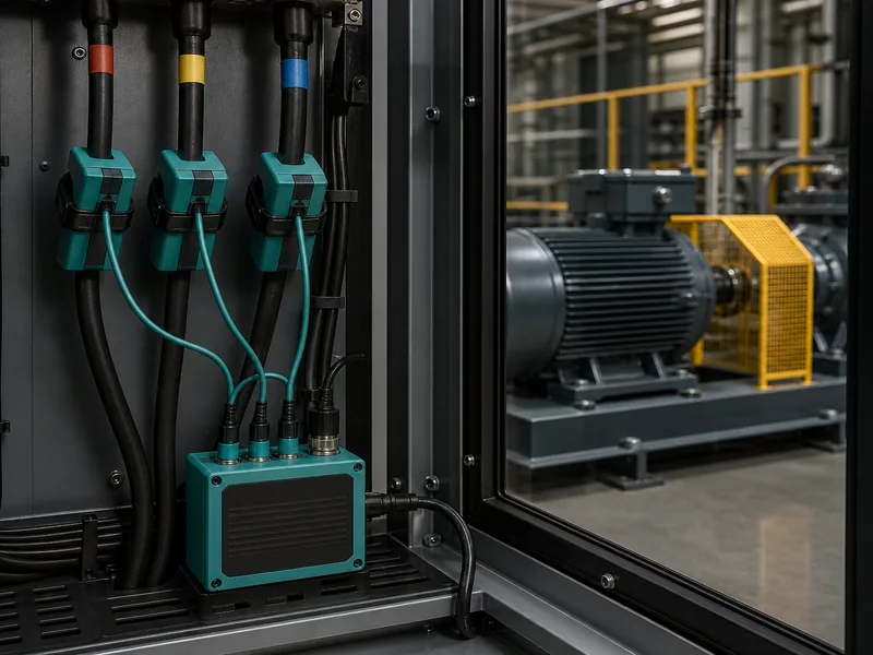
ConditionCore uses Motor Current Analysis (MCA) as its product-facing label for online motor current signature analysis, commonly abbreviated MCSA. The workflow is designed to accept three-channel motor-feeder line-current waveforms and spectra, preserve the motor, feeder, supply, drive, speed, slip and load context, then compare qualified signatures with the rest of the machine evidence.
Motor Current Analysis (MCA)
For an energized three-phase induction motor, keep the feeder, acquisition method, supply type, speed, slip, load and baseline attached before comparing signatures.
Illustrative online signature workflow
Illustrative · not a customer resultOnline current data becomes defensible evidence only when acquisition method, supply type, motor configuration, speed, load and a comparable baseline travel with it.
Qualified observation
This supports a targeted review, not a broken-rotor-bar declaration. Check phase voltage when available, load stability, speed or slip, motor design, vibration response and the driven machine before assigning cause.
Scope: online electrical signature analysis for energized three-phase induction motors, consistent with ISO 20958. This is not offline motor-circuit analysis. Line supply, VFD control and switching, voltage quality, driven-load modulation and acquisition settings can all shape the signature. Motor-feeder data collection must follow the site electrical-safety programme and be performed by qualified personnel. Installed acquisition hardware or de-energized installation is preferred where feasible.
Data in
Motor current is a machine-system response. Supply distortion, drive switching, motor design, speed, slip and driven-load variation can move or create spectral features. A current signature supports a hypothesis; it does not pinpoint GBX-2 or confirm a rotor, bearing or insulation fault by itself. This workflow follows the ISO 20958 scope for energized three-phase induction motors. Other motor and drive types require method-specific acquisition and interpretation.
What it can reveal
Assess current-signature features that may be consistent with rotor-bar or end-ring change.
Test expected signature families against motor design, speed, slip and load.
Retain channel and available voltage context before interpreting imbalance or distortion.
Qualify possible VFD switching and control influence before assigning machine cause.
Relate torque and driven-load modulation to the connected motor, gearbox, pump or fan.
Compare electrical signatures with vibration, thermal, ultrasonic and oil evidence without treating them as equal votes.
How ConditionCore uses it
Rotor, air-gap, supply and driven-load patterns in motor current, qualified by drive, speed, slip and load.
Retain raw line current, available voltage, channel mapping, feeder point, current-transformer setup and sample settings.
Retain line or VFD operation, motor data, sampling setup, speed, slip and load.
Assess repeatable signature change against a matched electrical and operating reference.
Test rotor, air-gap, supply or driven-load hypotheses against the rest of the machine evidence.
Common questions
See the controls required for a trustworthy comparison.
ConditionCore uses Motor Current Analysis (MCA) as its product-facing label for online motor current signature analysis, commonly abbreviated MCSA. ISO 20958 uses the broader term electrical signature analysis. This is distinct from de-energized Motor Circuit Analysis, which is also shortened to MCA.
Qualified signatures can support hypotheses involving rotor bars or end rings, air-gap eccentricity, supply or phase condition, drive effects, motor loading and mechanical torque modulation reflected through the driven train.
No. A driven-load change can modulate motor current, but current data usually cannot localize the physical source in the gearbox. Matched vibration, thermal, ultrasonic, oil and operating evidence are needed to test the mechanical explanation.
Potentially, but the drive output frequency, control state, switching environment and matched reference must be retained. A threshold developed for a line-fed motor must not be transferred without validation.
No. Motor current adds an electrical and drive-train view. Vibration usually provides stronger mechanical localization. Their value increases when each is allowed to test the other without being treated as an equal vote.
First machine review
Share one changing asset and the files you already have. We will confirm what is usable, what remains uncertain and which next check is most valuable.
Request a machine review